Lab 5 Writeup
Lab 5: Interrupts
Hours Spent: 23.2, Mapped with Toggl Track
Introduction
In this lab, a STM32L432KCU Microcontroller Unit (the MCU) was used to to read and print out the frequency of a 25GA-370 DC Motor. This lab made use of the STM32xx’s ability to plan responses to interrupts on the board, which in turn can be used to determine the direction and speed of a given motor based on the encoding of a given set of pins. This lab was framed to teach how to use interrupts and how to make use of Segger Embedded Studio’s printf functions.
Design
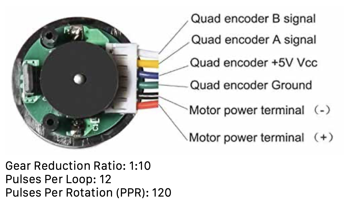
This lab requires the use of a TS-25GA370 DC motor. This motor has two separate voltage supplies (Figure 1): one that goes up to 12 V, and is responsible for rotating the motor itself, and the other is the encoder, which requires 5V, and is responsible for sending 5V signals out of the encoder pins, which can be read within this lab. There are two encoder pins that the motor sends out, pin A and pin B. These pins are offset by pi/2 radians, meaning that they behave similar to sine-cosine behavior, or to those that are familiar with it, IQ data in radio. Such a setup enables us to reconstruct received signals with only two data points, depending on whether the signals are rising or falling relative to each other at any given point.
Setup
I learned my lesson about timers after Lab 4, where I repeatedly tried changing the frequency of my timer only to run calculations for the accuracy of a frequency and realize that the itmer was wrong. Instead of going through the same pain this time, I chose instead to calculate beforehand the exact frequencies I would need to read out of my board so that I could properly set the timer’s prescaling.
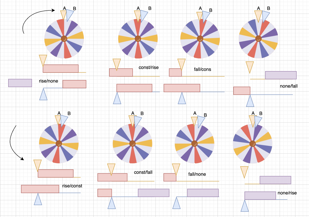
Firstly, I set up every scenario I would potentially run into within this lab in order to understand what cases I would need to check on the motors for absolute accuracy. I drew all eight of them, as seen in Figure 2, and determined that a full “period” of oscillation would actually be four interrupt signals received equal spacing apart. I decided that the best way to deduce frequency, as a result, would be to take the average of some past number of signals in order to determine the current speed of the motor.
I found two patterns separately that would help me determine both the speed and the frequency of the motor. Firstly, the motor has 12 “signals” that it sends to A, and the same number to B. As a result, every rotation there are a total of 12 pulses supplied by the motor via the quad encoder pins (Figure 1). Additionally, since the gear reduction inside the motor is 10:1, there will be 120 pulses received per every actual rotation of the external pin. Resultantly, whatever readout I would get from one channel (i.e. readin A, for example) would represent 1/120 of a total rotation.
As for the forwards or backwards spin, after drawing a step by step look at what would happen to A and B when the motor was rotating forwards versus backwards (Figure 3), I was able to construct a table (Figure 4) that described the behavior I was seeing.
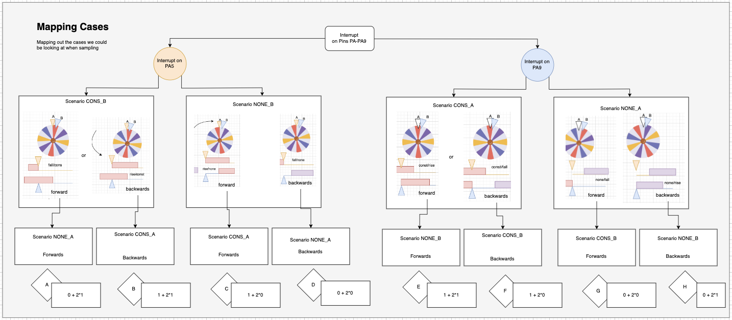
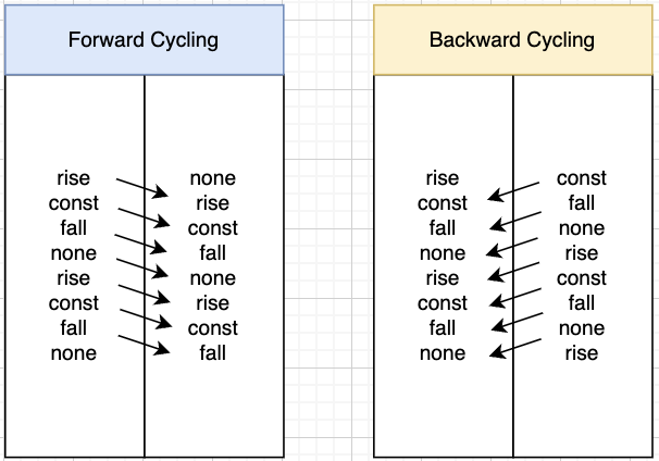
After this, I worked backwards to find the maximum and minimum frequencies that I would be required to collect considering the planned interrupts of my timer.
The datasheet for the motor states that the motor can run between 10-600 rpm. When calculated into rotations per second, or more specifically the number of signals per second you get the following function:
\[ 10 rpm * \frac{120 pulses (A and B)}{1 rotation} * \frac{1 minute}{60 seconds} = \frac{20 pulses}{1 second} \]
This would mean that, in order to get the minimum number of samples possible to see this frequency, I would need to be able to sample at at least 40 Hz. For the sake of safety, I additionally said that I should be able to see up to 8Hz (i.e. one full period of an A and B signal rising and falling).
For the maximum frequency of 600 rpm, I pretended we were instead going to measure maximum 800 rpm. This meant, according to the math seend above, that I would need to sample at a rate of 3200 pulses every second in order to not miss any of the samples I was expecting to see.
With this in mind, I began deciding on the timer that I wanted to design; most timers on the system are already based off of the HCLK clock, or th 4MHz clock, that already exists in the system. I started first by figuring out how if, at minimum, I wanted to be able to to read out a 8Hz signal, I would need such a time period between Timer ticks that filling the entire ARR array of a timer would take longer than it would take to receive an 8Hz tick. To do so, I computed the period of 8Hz (\(1/8\) of a second) and then multiplied it by 65535, or \(2^{16} - 1\), which is the maximum value that can be reached with the ARR variable. I then took the inverse of this to find that the maximum frequency I could possible do, while still being able to sample the 8Hz signal, was 524,280 Hz.
As a result, I found that the general range in which I would be safely able to sample the rotations of the motor were between 3200 and 524280 Hz. Of these, I decided that it would good to have a clock frequency of 300,000.
Planning the Code
My intention within this project was to build a running average that I could use to measure the average speed of the motor. To do so, every interrupt the code would increment the index of a given array (either moving forwards or back to the beginning depending on its location), and the interrupt would call two functions to determine what was happening. I intended to use pins PA6 and PA9 for this system, since both pins are able to withstand 5V of power (pages 52-54, Table 14, of the STM32L432KC Datasheet). In addition, these pins are already connected to the same interrupt pathway, which meant that I would only need to control one interrupt handler to understand what was going on in either pin at a given time.
Pre-Code
Segger Embedded Studio 8.16a was used to program all modules. In order to make sure I knew what needed to be done to handle an interrupt, I constructed a smaller project for creating an interrupt with a button, which would toggle and LED on and off.
To control an interrupt, there are X main steps:
- Enable the SYSCFG clock to get to your desired pin, and enable your pin.
gpioEnable(GPIO_PORT_A); pinMode(PA5, GPIO_INPUT); RCC->APB2ENR |= (1<<0);
- Set the configuration of the EXTI control register to the right value. This can be done using the SYSCFG structure that has come with the given STM32 headers. For those that noticed, the array of the EXTICR is indexed from 0, not from 1, even thought the names of the variables are indexed from 1: as a result, if I want to control the EXTI Control Register 2, I have to call
SYSCFG->EXTICR[1], since the bits at [2] would actually be for control register 3.
SYSCFG->EXTICR[1] &= ~_VAL2FLD(SYSCFG_EXTICR2_EXTI5, 0b111);
Enable global interrupts via the code
__enable_irq();Configure the code so that the triggers arrive on the right spots. First, I configure the GPIO pin I would be using to trigger the LED (PA5) to be read as if it were intended ot be used for an interrupt request. I then set it such that it would trigger an interrupt only on the falling trigger, not the rising edge.
EXTI->IMR1 |= _VAL2FLD(EXTI_IMR1_IM5, 0b1);

// 2. Disable rising edge trigger
EXTI->RTSR1 &= ~_VAL2FLD(EXTI_RTSR1_RT5, 0b1);

// 3. Enable falling edge trigger
EXTI->FTSR1 |= _VAL2FLD(EXTI_FTSR1_FT5, 0b1);- Finally, turn on the EXTI interrupt from within the Nested Vector Interrupt Controller (NVIC), specifically via the ISER register.
NVIC->ISER[0] |= (1 << EXTI9_5_IRQn);
I then set up my button so that it was a pull-up resistor, and then set the DIP Switch button to pull it down to 0 when it was pressed. I was able to confirm, in this way, how interrupts worked via GPIO pins, and was able to expand this into my final code.
Code
My code consists primarily of only a c file and a header file this time (main.c and main.h).
main.c: a C file that initializes and configures all the addresses and registers as required by the system. Additionally provides helper functions for the main that will be triggered or used by the triggered function
EXTI9_5_IRQHandlerto control the current array that is tracking the frequency.main.h: Assigns the A and B input pins from the motor, as well as labels two timers (TIM2 and TIM6, specifically) as the clocks that will find the frequency or will be used for printing and delaying between prints.
Since I only wanted to update the printout statements every second, I used the delay_millis with Timer 6 to wait for the requisite amount of time before running again.
Global Variables
I configured my main file with a set of variables that could be used for two purposes; first, to keep track of the current number of ticks for the frequency, and second, to help the system work at extremely low frequencies. The variables are listed in the table below, with corresponding functionalities next to them (Table 1)
| Variable Name | Purpose |
|---|---|
| volatile int arrA[5] | An array of counts: keeps track of how many counts have passed between each tick on the motor via TIM2->CNT; only changed when pin A triggers an interrupt |
| volatile int arrB[5] | An array of counts, like arrA. The only difference is that it is changed when pin B is triggered |
| volatile int idxA | The index that is set to next be changed in arrA when the system is triggered by an input from pin A |
| volatile int idxB | The index that is set to next be changed in arrB when the system is triggered by an input from pin B |
| int hav_ent | Whether or not we have entered an interrupt statement within the current loop of TIM6 (i.e., has an interrupt been triggered in the past second). This is used to determine whether or not the motor is actually spinning, and stalls the system for ten seconds until it determines that there is no signal. |
| volatile int curr_count_avg | Is recalcualted every loop of the timer cycle. Finds the average amount of counts between an A to B signal or a B to A signal by averaging the values of arrA and arrB. |
| volatile int forwards | Changed within the interrupt loops. Determines whether the system is moving forwards or backwards (i.e. clockwise or counterclockwise) |
| volatile int first_time_loop_A | Used at the very beginning of the system. Waits for the user to start moving the motor before it tries calculating average time. |
| volatile int first_time_loop_B | The same as first_time_loop_A, except this time triggered by an interrupt from encoder pin B. |
| double frequency | The frequency of the system itself. It is equivalent to \(\frac{30000}{4 * curr_count_avg * 120}\), since the samples have been collected at 30000 Hz. |
This design is set to trigger on every edge of the potential interrupts that we’d see from pins A or B. The additional calculations confirm that it will be able to read both extremely low signals, and the fastest possible signals from the motor (i.e. the 10Hz signal when it is powered at 12 V).
Additional Modules
This code also makes use of the <stdio.h> header library, as well as the _write function that comes with the the printf library. This library (if you forget to import it or weren’t aware that you needed to when initializing your project) can be added to your *.emProject file, as depicted below (Figure 5).
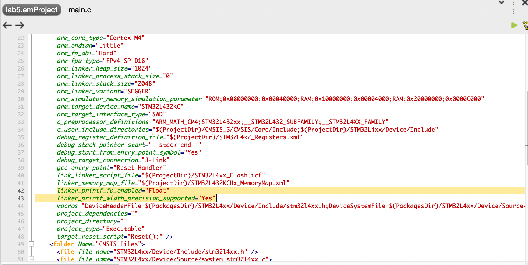
The printf statement applies, as far as I see, only to the Debug Terminal. Resultantly, when running your code in in Debug mode, and chose to play by itself (the green arrow), you will see the terminal consistently update depending on what’s in your printf statements. In my case, I chose to update based on a variety of factors, mainly being
Whether or not we had just started the program
Whether the signal was arriving extremely slowly
Whether the motor was turned on or not (if it had already run)
How fast and in what direction the motor was moving.
All of these print statements I set to be called by the main function through a series of if statemeents.
Why Interrupts?
Consider that you were trying to toggle an LED pin; inside of a simple while loop, you could simply check to see if a button was pressed, and set the LED. But if that while loop contains additional code, all of a sudden it is possible that the button could be asynchronously pressed, and you would completely miss the trigger to turn the LED on. This is the primary motivation for using interrupts with your MCU.
For this code, in particular, we must keep in mind that the print statement is updating every 1 Hz, we won’t be able to check how fast the motor is running using this timer accurately. The most we could likely do would be to wait one millisecond, and check to see if we have an input, and do this method 1000 times. But the problem is that sometimes, waiting a millisecond could take longer than another because of the interrupt, or because of other processes on the chip. As a result, the program would inconsistently update its timer value (i.e. the updates wouldn’t always happen every second, and may take more time to arrive if the interrupts or if additional system processes are happening faster). Additionally consider what happens if you want to do more than just check for the motor interrupt - maybe this was a system that was measuring temperature underwater on a submarine, and the motors just need to be checked every so often to make sure that they aren’t stuttering or we haven’t hit a wall. In that case, there would be far more items to check off via manual polling, and it may sometimes take far to long to reach the frequency readouts; if that’s the case, they either wouldn’t be accurate, or would be missed altogether. Since motors rely on square waves, if you happen to sample the wave when it’s at 0, it will appear as if the motor isn’t on; it is only through consistently tracking when the motor changes its value that you can caccurately measure its frequency, and this is why interrupts are so useful.
Final Setup
The final layout for this program can be seen in Figure 6.
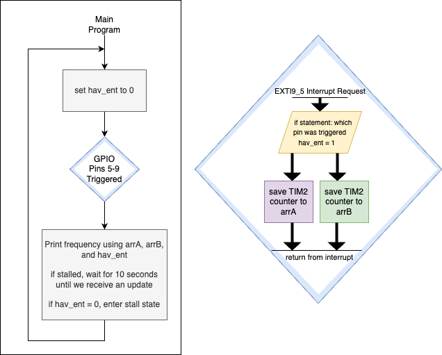
The program prints values every second. These values are determined after 1 second of waiting, and are calculated using the arrA and arrB vectors, which have the number of counts between each interrupt saved for the past 5 interrupts. At the very beginning of main’s while loop for this system, the variable hav_ent is set to 0; if it remains 0 the entire time, that means that there has been no interrupt within the 1 second delay, and the system enters a stall state. To allow for extremely slow frequencies, the system will wait for 10 beats; if hav_ent has not been set by this time, then the program assumes that the motor is not running, and prints out a variable saying as much.
Hardware Setup
All that was required for the setup of this lab was the TS-25GA370 DC Motor and pins to read the input (PA6 and PA9), as well as to supply 5V and GND to the encoder pins on the motor. The motor was supplied separately with between 0-12V, as demonstrated in the schematic (Figure 7)

Pins PA6 and PA9 were chosen, individually, becuase they are able to withstand 5 V of power as opposed to other pins that can only take in 3.3 V. This is detailed further in Table 14 (STM32L432xx pin definitions) in the STM32L432xx Datasheet.
Initial Testing
To make sure that this system could initially run, I used the demos Python proram “interrupt_button.c”, which still remains in the project even though it is excluded from the build. I could easily use this button configuration to confirm that my interrupts were set up correctly, which aided a large part in debugging.
Results and Discussion
In conclusion, this lab was a success in configuring an MCU board to use interrupts for measuring the velocity of a motor. It additionally provided information about the incorporation of printf statements within a program, which will prove helpful in later labs for debugging purposes.
Conclusion
In conclusion, all of the program works properly in simulation and in hardware, and can be confirmed with the use of an oscilloscope or a callibration plot that accounts for the voltage to spin rate of the motor.
I spent a total of 23.2 hours working on this lab, with roughly three of them spent on the lab writeup, and two spent building the initial diagram of what signals I anticipated to see with the spinning motor.